
Challenge Description
With the generous help of the folks at 3D4E, I finally have a flag that can literally be captured! I made sure to document this incredible accomplishment, though my microphone was busted.
This is not an OSINT challenge, and the video is the only thing you need to solve the challenge. Please do not try to research the challenge author or any other organizations mentioned in the description. It will not help.
TL;DR: Extract a flag from a 3D printer’s toolpath by tracking the printhead and bed movement through video analysis.
I downloaded the video file and started analyzing it. My first instinct was to check if there was any hidden information in the audio track, especially after reading this writeup about audio side-channels.
ffprobe -hide_banner -show_streams -select_streams a videoplayback.mp4
ffmpeg -hide_banner -i videoplayback.mp4 -vn -af volumedetect -f null -Results: The video contains an AAC audio stream, but it’s essentially silence (mean_volume: -91.0 dB, max_volume: -91.0 dB). Dead end.
Failed Approaches
Attempt 1: Simple Template Matching
I started with a lightweight computer vision approach:
- Used template matching on downscaled frames
- Tracked printhead and bed patches frame-by-frame
- Reconstructed relative 2D path
- Filtered large jumps as travel moves
- Rasterized remaining short segments
Problem: Bounding boxes drifted over time, fallback matching occasionally snapped to wrong regions, and final output was too noisy to read.
Attempt 2: Physical Constraints
I tried using actual 3D printer kinematics and rough physical measurements to constrain the motion model more accurately.
Problem: Camera perspective distortion, unknown printer geometry, and cumulative template drift introduced too much error. This approach wasn’t stable enough for the ~2 minute drawing sequence.
Working Solution
Key Insight
The flag is being “printed” by the nozzle moving relative to the bed. By tracking both objects independently and computing their relative motion, I can reconstruct the toolpath in printer coordinate space—ignoring camera movement entirely.
Implementation Strategy
I built an interactive tracker with manual region selection using polygon corners instead of simple bounding boxes. This gave much more stable initial tracking points.
Timeline note: The actual flag-writing starts at approximately 7:15 (frame 13020), so I skipped ahead to that point for ROI selection.
Technical Breakdown
Full implementation available here: solve.py
Step 1: Dual-Object Tracking
For each frame, I track two regions:
- Nozzle center:
(nozzle_cx, nozzle_cy)— the printhead position - Bed center:
(bed_cx, bed_cy)— a fixed reference point on the print bed
Tracking method (with fallback):
- Try OpenCV tracker update (CSRT/KCF)
- If tracker fails → masked template matching near last known location
- If both fail → use previous frame’s position
Step 2: Coordinate Transformation
Convert from camera coordinates to printer-relative coordinates:
# Relative motion (nozzle position relative to bed)
print_X_raw = nozzle_cx - bed_cx  # X motion: nozzle moving horizontally
print_Y_raw = bed_cx              # Y motion: bed moving (this printer is bed-slinger style)
This works because:
- The nozzle moves in X
- The bed moves in Y
I then apply high-pass filtering to remove slow drift:
def high_pass(signal, window=500):
    smoothed = moving_average(signal, window)
    return signal - smoothed

print_X = high_pass(print_X_raw)
print_Y = high_pass(print_Y_raw)
Step 3: Travel Move Detection
Not all motion is drawing. The printer makes rapid “travel” moves between letters without extruding filament. I detect these by computing per-frame speed:
raw_speed_comb = sqrt((Δnozzle_cx)² + (Δbed_cx)²)Threshold: Speed > 2.0 pixels/frame = travel move (non-drawing)
Step 4: Path Segmentation
Split the continuous path wherever speed exceeds threshold:
- Keep only segments with ≥2 points
- Discard isolated points and travel moves
- This leaves only the actual “drawing” strokes
Step 5: Orientation Correction
# Flip both axes
fx = -nozzle_cx
fy = -bed_cx

# Then rotate the final rendered image 90° counter-clockwise
rotated_img = cv2.rotate(img, cv2.ROTATE_90_COUNTERCLOCKWISE)
These transforms were determined empirically by trying different orientations until text was readable.
Step 6: Visualization
Render cleaned segments with matplotlib:
- Line width: 2.0 pixels
- Equal aspect ratio (no distortion)
- Only draw filtered path segments (no travel moves)
Results
Recovered flag: lactf{4n_irl_fla6_f0r_onc3}
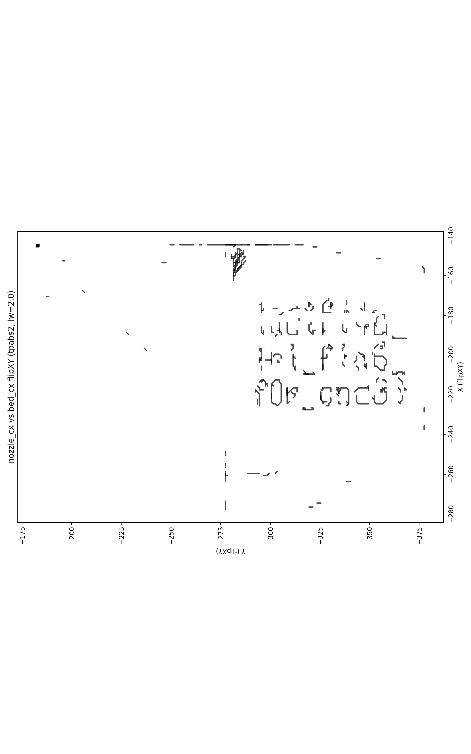
The text reads clearly after orientation correction. The flag is leetspeak for “an irl flag for once”
Shout out to my teammates at RaptX because we went absolutely crazy trying to read it 😂
Even with the recovered image, the text was barely readable. We spent way too long squinting at noisy pixels trying to figure out if that was a 6 or a G, whether 0 was O or 0, and debating if onc3 was even a word 😅
Context & Related Work
This challenge explores optical side-channel attacks on 3D printers—a real security concern in manufacturing. Recent research has demonstrated that G-code instructions can be reverse-engineered from video recordings using deep learning methods:
“One Video to Steal Them All: 3D-Printing IP Theft through Optical Side-Channels”
Chattopadhyay et al., 2025 — https://arxiv.org/html/2506.21897v1
Their approach uses ResNet-50 + LSTM neural networks to predict printable G-code from 30-frame video chunks. My CTF solution is significantly simpler: I used classical computer vision (OpenCV tracking + template matching) to extract a 2D trajectory, since I only needed to recover readable text, not full G-code.
Key Principles
These are the core ideas I used:
-
Side-channel reconstruction: Toolpaths can be recovered by tracking moving printer components over time
-
Relative motion matters: Camera coordinates ≠ printer coordinates. Track nozzle position relative to bed, not absolute screen positions
-
Motion classification: Separate print moves from travel moves via speed thresholding. Otherwise rapid positioning clutters the output
-
Orientation ambiguity: Monocular video has inherent flip/rotate ambiguities. Trying different orientations is standard practice
The challenge only required recovering 2D text—much easier than the paper’s goal of generating complete, printable G-code with extrusion timing and feed rates.